
The test tower for the M4, the wavefront corrector for the ELT, is now ready for final integration!
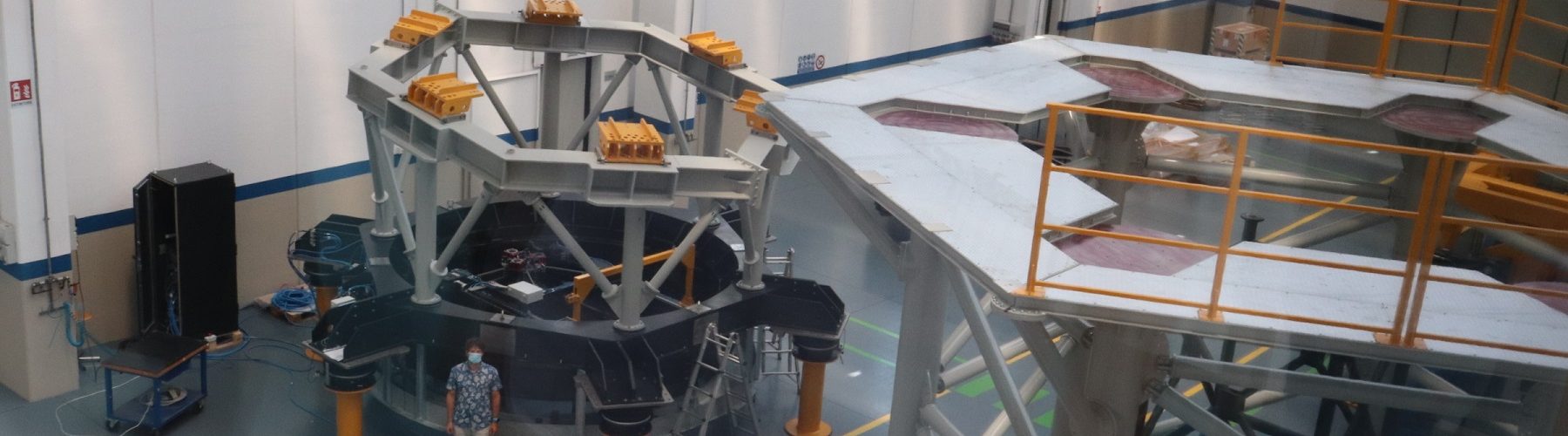
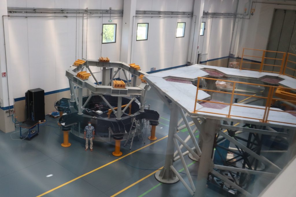
The system review held on Tuesday July 21st, with (either in person or remotely) ESO and the AdOptica consortium. The system is currently separated into two parts: the support for the interferometric tower, composed by 6 giant feet, 4 m high with a panoramic platform on top, and the interferometeric tower itself, with the cells for the optics and the actuators to aitm at the different M4 segments. ADS International (partner of the AdOptica Consortium) is responsible for the design and integration of the system, and translated into mechanical items the optical design and the test procedure prepared by the INAF team, during the Optical Critical Design Review phase.
Let’s go neatly. M4 is a 2.5 m diameter, flat mirror, divided into 6 segments (or petals), each controlled by 892 voice-coil actuators. How would you measure a flat mirror? You need a collimator, an optical system to expand the laser beam from the interferometer to the desired size. This task is done with a parabolic mirror, which is fed from its focus (3.5 m high) with a diverging laser; the parabola sends back the collimated beam toward a M4 segment. That’s when you need a big brush…
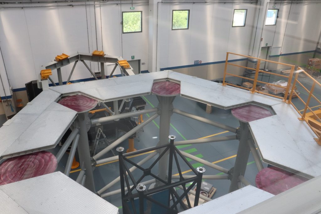
View of the external support with the optical bench (black) 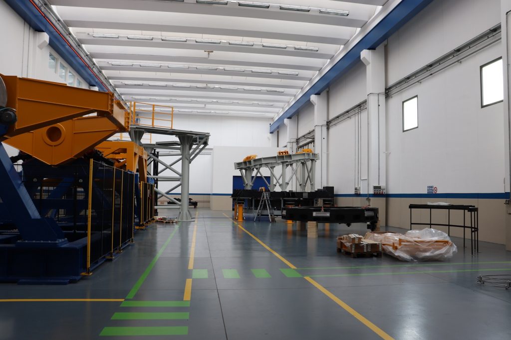
View of the integration hall at ADS.
You will not see the entire mirror, this way! You’re right, you get one segment each time. However, from the control point of view, this is not an issue, since the actuators are controlled indipendently segment per segment. So i can measure a single segment and command its actuators only. Or, more elegantly speaking, is can use block-diagonal control matrices and null, time by time, the blocks corresponding to currently non visible actuators.
Biuld your own test tower for M4! you need:
- a circular rail to move parabola and interferometer and aim the various segments;
- a linear rail to move along the M4 diameter and aim at the M4 center (and co-phase the segments)
- a moving cart to hold a flat reference mirror, to put it inside/outside the cavity and run the optical alignment;
- motors, enough to align the parabola and the flat reference;
- parabola and flat reference, polished down to a few nanomenters;
- a very fast interferometers, with many pixels.
And if you need more information how to use it, check the out here:
Don’t miss the next episode! We will tell you the tests and verifications on the tower, to sniff all the potential sources of problems and run an optical test like a pro!